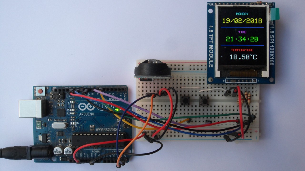
- Ds3231 use as timer generator#
- Ds3231 use as timer code#
IIC bus interface, the maximum transmission speed of 400KHz (working voltage of 5V). Memory chips: AT24C32 (storage capacity 32K). The chip temperature sensor comes with an accuracy of 3 ℃. Ds3231 use as timer generator#
Real-time clock generator seconds, minutes, hours, day, date, month, and year timing and provide valid until the year 2100 leap year compensation. Clock Accuracy :0-40 ℃ range, the accuracy 2ppm, the error was about 1 minute. Clock chip: high-precision clock chip DS3231. It is a good substitution for the data logging shield, with even higher time precision. Besides, there is also an EEPROM AT24C32 to supply you with 32K EEPROM to store your data, it is the best choice for your application that needs recoding time, a built battery holder makes this module suitable. Unlike the DS1307, the DS3231 also has an integrated crystal (so no external crystal required), temperature sensor, 2 programmable time-of-day alarms, a 32.768 kHz output pin to ensure higher accuracy. Compared to the DS1302 solution, the DS3231 has many advantages, it functions with a VCC ranging from 2.3V to 5.5V and has a battery backup. RTC Real Time Clock and EEPROM DS3231 AT24C32 Module - DS3231 is a low-cost, extremely accurate I2C real-time clock (RTC), with an integrated temperature-compensated crystal oscillator (TCXO) and crystal. The DS3231 real time clock communicates with the Arduino through the I2C communication, so we have included the wire library.RTC Real Time Clock and EEPROM DS3231 AT24C32 Module 
The wire library is for the I2C communication between the DS3231 and the Arduino.
Ds3231 use as timer code#
VCC on the DS3231 to the 5V pin on the Arduinoįinally, connect the positive of the buzzer to pin 11 on the Arduino and the negative the of buzzer to GND on the Arduino.Īrduino Alarm Clock Code #include #include #include LiquidCrystal lcd(2, 3, 4, 5, 6, 7) DS3231  rtc(SDA, SCL) Time  t #define buz 11 int Hor int Min int Sec void setup() Code Explanation First of all, we included the libraries for the DS3231 real time clock and the LCD. GND on the DS3231 to GND on the Arduino. Then connect the DS3231 real time clock module to the Arduino as follows: This is the negative pin of the backlight. This is the positive pin of the backlight. Pin 15 to the 5V pin on the Arduino through the 220- ohm resistor. Connect the data pins (D4-D7) to the pins 4, 5, 6, 7 on the Arduino. Pin 6 on the LCD to the pin 3 of Arduino.  Pin 5 on the LCD to the ground of Arduino. Pin 4 on the LCD to digital pin 2 on the Arduino. Pin 3 on the LCD to the middle pin on the 10K potentiometer. Pin 1 on the LCD to ground on the Arduino. Circuit Diagram Connect the LCD to the Arduino as follows: The time and date will also be displayed on the LCD. The beeping time in our code is 2 minutes, but you can increase it as much you want. If the current time matches with the alarm time, then the buzzer will start to beep. We will get the time and date from the RTC module using the library functions and then we will compare this time with the alarm time that we have set in the code. It has a built-in 3V battery, which keeps updating the time.
How Does the Arduino Alarm Clock Work? The DS3231 real time clock module keeps track of the time even when the module is not powered.


 0 kommentar(er)
